Magnetooptical techniques are commonly used for thin and ultrathin magnetic film study. Fig. 3.1 shows results of interaction of linearly polarized light with perpendicularly magnetized film in : (i) the transmitted mode – Faraday effect; (ii) reflected mode – Kerr effect. We focus our analysis on Faraday effect application on thin magnetic films study.
 |
| Fig. 3.1. Scheme of the Faraday and Kerr effects. |
Domain visualization by the Faraday effect in transmitted light mode.
Fig. 3.2 shows a scheme of the Faraday effect application for magnetic domain image formation. Unpolarized light passes through a linear polarizer, P. The polarized light is then incident on a magnetic film with two types of domains with opposite directions of magnetization, M.
 |
| Fig. 3.2. Scheme of experimental set-up for domain imaging using the Faraday effect. Parts A and B correspond to opposite angles between analyzer – polaryzer. Images of selected domain structure (in a garnet film) registered for different a are also shown. (Animation – visualization of magnetic domains ) |
The image formed by the transmitted light carries with it information about the domain structure of the crystal. This information is represented by intensity of the light in the final image, and the intensity is dependent on the local vector of magnetization in the crystal and the angle a between the polarizer and analyzer.
The Faraday rotation angle is φF and –φF in the two domains, respectively, see Fig.3.2. Because of the Malus law the light beams after passing the system (polarizer, magnetic film and analyzer) have different intensity which obey
 |
(3.1) |
where I0 is intensity of the incident light. The light intensities from two domains are different:
Hysteresis loops registration using the Faraday effect
Magnetic film could be also studied using a single detector registering light passing many domains, see Fig. 3.3.
 |
| Fig. 3.3. Scheme of experimental set-up for hysteresis loops registration using the Faraday effect. |
Let us consider the linearly polarized light passing through the sample with magnetization M induced by external field H. The light polarization plane rotates by the angle φ=m φF, where m is the normalized magnetization m=M/MS. So the light intensity on the detector could be described by
 |
(3.2a) |
and signal measured by the detector
 |
(3.2a) |
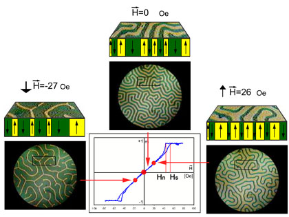 |
| Fig. 3.4 Magnetic field induced changes of domain structure geometry and hysteresis loop measured in the garnet film. |
Fig. 3.4 shows the magnetization structure of a garnet thin in the presence of an external magnetic field. In equilibrium, without external magnetic field, the state of this uniaxial magnetic film has two oppositely oriented magnetic domains, both of which lie normal to the film plane. These domains exhibit a stripe-like labyrinthine structure. “Up” and “down” directed domain have almost the same volume at zero field H. When a magnetic field is applied in the direction of one domain magnetization, that domain becomes dominant, as can be seen in Figs. 3.4a and 3.4c.
These films with perpendicular anisotropy have been designed for use in bubble domain memories devices (a magnetic bubble is a small, stable cylindrical domain of reverse magnetization perpendicular to the surface of a thin magnetic film).